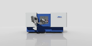
SIMAG IG 400 CNC
Specifications
| Manufacturer | SIMAG |
| Model | IG 400 CNC |
| Condition | New |
| Stock Number | in fabbrica |
Description
Base
Natural granite base “Nero Africa”
• 2 rear coolant-lubricant discharge ports
3 anti-vibration levelers
Axis X (Radial translation of the tool carriage with spring)
Driver with ground and preloaded ball screw drive IT1
Alpha axis motor i-D, absolute encoder, without battery.
Absolute Fagor optical ruler with resolution 0.01 μm
Drive shaft with precision ground recirculating ball screw and preloaded IT1
High-precision roller circulating guide
Z-axis (Axial translation of the spring carriage)
Driver with ground and preloaded ball screw drive IT1
Alpha axis motor i-D, absolute encoder, without battery.
Absolute Fagor optical ruler with resolution 0.01 μm
Drive shaft with precision ground recirculating ball screw and preloaded IT1
High-precision roller circulating guide
U-axis (radial translation of the part-holding head)
Driver with ground and preloaded ball screw drive IT1
Alpha axis motor i-D, absolute encoder, without battery.
Absolute Fagor optical ruler with resolution 0.01 μm
Drive shaft with precision ground recirculating ball screw and preloaded IT1
High-precision roller circulating guide
Axis B (Angular tilt of the workpiece head)
Alpha axis motor i-D, absolute encoder, without battery.
Angular accuracy < 1”
• Belt drive with reducer
Hydraulic parking brake
Pneumatic support
UT Axis (electromandrel revolver)
• Torque rotary table
Absolute Fagor encoder with 1” resolution
Hydraulic parking brake
Rotation on high-precision preloaded roller bearing
Clamp C (Workpiece Holder Head)
Alpha axis motor i-D, absolute encoder, without battery.
• Rotation on high-precision ball bearings
Pneumatic clamping for manual movement of the workpiece head
Grinding tool holder chuck
• N.1 internal spindle motor Fischer 60,000 rpm
• N.1 internal spindle motor Fischer 42,000 rpm
No.1 external spindle RPM / Peron Speed
Cooling with water-glycol chiller
Independent centralized lubrication for each electrospindle via pump and micro
SKF-Vogel injectors.
Management of wheel/part contact via monitoring of current absorption (not provided)
AE)
High-frequency Nidec inverter with braking resistor, for dynamic stopping of the grinding wheel
Brush group
Position 1: fixed diamond support
Position 2: available
Touch sensor group
Electro-activated probing arm complete with Marposs T25 probe
Hydraulic system
Hydraulic power unit equipped with all the components necessary for proper operation of the
machine (pump, downstream filter, solenoid valves, pressure switches, etc.)
• All components used are from primary companies and easily available (Rexroth, Atos, MP)
Filters, IFM, etc.)
Pneumatic plant
• Pneumatic system equipped with all necessary command and control components for proper
machine operation (insertion valve general, TFR unit, pressure switches,
solenoid valves, etc.)
All components used are from primary companies and easy to source (Festo, Pneumax,
ecc.)
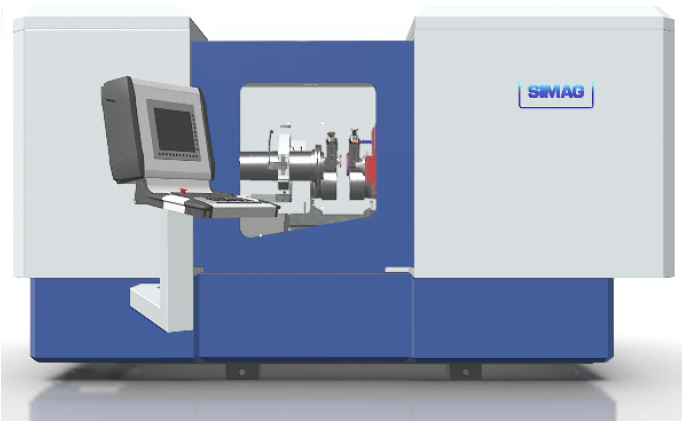
Machine housing
Full machine casing
Front sliding door manual equipped with safety electro-lock and glass
anti-foundation
• Removable perimeter panels for inspection, cleaning and maintenance operations (all panels
they are equipped with a safety magnetic sensor.
Electrical and Software Part Description:
Electrical panel, with all necessary components for the machine to operate.
The CNC unit will be Fanuc:
or CNC 0iF-plus
the 15-inch Touch Monitor
the full keyboard
the machine panel
Portable switchboard with flyer
the Alpha i-D drive group
Alpha i-D axis motors, equipped with absolute encoders, battery-free, with 4,000,000 pulses
rotation.
• The X, Z, U and B axes will also be equipped with absolute linear position sensors (Fanuc protocol), resolution
0.01 μm
The UT axis is equipped with a Fanuc absolute encoder, resolution 1”
• The grinding spindle motors will be driven with a high-frequency inverter (up to 3000 Hz) Nidec-
Technical Control, HS70 series, with braking resistance, for rapid stopping
Management of the wheel-workpiece contact, using specific inverter functions for the wheel
Electrical Schema:
Electrical schematic design with Spac system, including:
Functional
Topographic
Terminal blocks
Machine-side connections
Bill of Materials
Electrical Panel:
Supply and wiring of electrical cabinet (standard carpentry color RAL7035 brushed Zanardo).
Main features:
General switch with fuses and external side or front operating device
• 400Vac power circuits, with individual magneto-thermal protections for the lines of
power supply, with indication of intervention on PMC input
• 24V auxiliary circuits, with separation of the various circuits, individually protected with switches
automatic, with alert of intervention on PMC input
Preferred material Schneider Electric
24V DC power supply suitable
• 220V lighting, with internal transformer
Service outlet protected by residual current device
Cosmotec-Stulz air conditioner
Machine edge connection to terminal strip
Fanuc Alpha i-HVD Axis Drive Group with network filter for EMC compatibility
• CNC Unit Fanuc 0iF-Plus
Fanuc Slice I/O input/output modules. Safe input/output boards will be included for the
safety features
Command console:
Supply and installation of command pulpit on adjustable arm.
On the podium, the machine control organs will be integrated, in particular:
iH-Pro Fanuc Panel Video Panel:
the 15-inch color LCD display
capacitive touch screen
Fanuc MDI Unit Keyboard, QWERTY
• BK15 machine control panel with customized keys for specific machine functions,
override axes and spindle
22-diameter control pushbuttons
• Portable IP65 control panel, with:
and the 5 m Cable
the quick connect to connector
or Selector axles
or Increment selector
the electronic flyer
The emergency stop button compliant with EN ISO 13850
The enable button, with axis stop management in Category 1 according to EN 60204-1
Electrical System:
Realization of the complete machine onboard system
Provision and installation of all connection cables to sensors and actuators (all cables
will be for mobile installation, oil-resistant), including suitable fixing systems (pipes, channel,
hardware store, etc.).
Supply and installation of auxiliary control panels (replacements, tool changer, etc.)
Supply and installation of any terminal strip connection boxes
Safety:
The operator protections/safeguards will be managed using Fanuc's Dual Check Safety.
With this option, the safety input/output signals (Emergencies, door limit switches, enablement)
grinder), they are managed in dual channel by two PLCs, with cross-checked control logics.
In addition, the numerical control is able to activate safety functions that meet the requirements of the
Category 3 as well as the Performance Level PL d according to DIN EN ISO 13849-1 and the Safety Integrity
The planned functions are:
Safe lockout (SS1)
During the intervention of a watchdog or an emergency, the actuations stop safely
Safe Operational Stop (SOS)
Monitor the drive systems in the stopped state. In this phase the drives are
fully operational and in position regulation. The function will be activated with the opening
of the operator door
Safe Reduced Speed (SLS)
Surveillance of designed speed limit values, which are activated in particular with the use of the
manual pushbutton with guards open
Safety input/output signals (DCS)
Interface to the process (door limit switch, emergency stop button, enable button,
power supply for electromechanical movement devices), with dual-channel connection,
managed by two PMCs
With the door open it will be possible to command the axes at reduced speed, in JOG mode, with action
held on the portable control panel's enable button.
By releasing the button, you will have a safe axis stop.
The grinding wheel rotation or diamond roll will not be possible.
Software
• Study and development of PLC software for the management of machine components and CNC interface
• Dedicated operating surface that allows the work program to be carried out, through a
sequence of cycles, selecting them from those available (Dive, Swing, etc.).
Each cycle is accompanied by a series of geometric parameters (positions and magnitudes of
machining, and technological parameters (turning removal, wheel speed and workpiece holder)
For executing the program, there is the option to select which
sequences/processing to perform and which not to do.
There is a tuning area that allows the adjustments of the
machine for processing, like diamond dressing, grinding wheel shaping, dressing workpiece,
definition of lockouts
In all these operations, the user is guided by graphics with the possibility of
self-learning of positions.
For the grinding profile, simple parametric profiles are available, manageable with the
simple parameter entry. Complex profile mole also possible,
configurable through an integrated graphical editor or by direct writing of the
ISO program or import of a profile in DXF format.
The application replaces the standard CN interface. For this reason, the following are available
display, setup and diagnostic pages, to ensure that all are present
the tools needed to use the machine, without having to access the interface
standard of numerical control, which can still be recalled, for use
machine generic or for system settings and general tuning of the
numerical control.
Connection to company network:
On the CN there will be an Ethernet connection, from which it is possible to access the CN,
using Fanuc libraries (FOCAS, not supplied)
The video panel is effectively a personal computer with Windows 10 IoT Enterprise 2016, equipped with
4 USB connections and 4 Ethernet connections.
• One of the USB ports will have a Wireless antenna installed, for connection to a WiFi network.
AnyDesk remote connection software will be installed for remote assistance.
NOTE: The remote assistance requires access to an Ethernet or Wi-Fi network that provides visibility
on the internet at Anydesk. If it is not possible, due to restrictions imposed by the corporate network, it is
anyway feasible over WiFi, with support on a mobile phone's hotspot.
Documentation
Electrical schematic on paper support in A4 format
USB Key contents:
Backup of CN and drive parameters
the PLC Program
PC hard disk image after commissioning, for rapid recovery
the electrical schematic in printable format (PDF)
Machine-specific operation manual in PDF format
Documentation specific to the components used
Operation and Programming Manuals Fanuc 0iF-Plus
CE certification of the machinery
The plant will be designed based on safety criteria and ease of operation; it will therefore
CE marked according to Machinery Directive 2006/42/EC and Low Voltage Directive 2006/95.